Introduction
When building a “new” PC one of the components that enthusiasts often pay less attention to, or often reuse, is their power supply. And, why not? For the most part, the ATX12v/EPS standards over the years have not changed nearly as much as other facets of the market and, barring some issues with efficiency and low power sleep states, most of the changes that have impacted power supplies are not noticeable to the end-user so long as they push the “on” button and their system powers up.
Therein we find one of the problems. What happens when you get everything installed in your brand new shiny case and you hit the power button………………..and nothing happens?
After you stop swearing, you start the, sometimes, long and arduous task of troubleshooting. Did you add the magical extra motherboard standoff? Did you not seat a connector right? Were you the guy who got the PCI version of the Voodoo 3 crammed into an ISA slot? What now?
Well, most of the time you swear some more as you painstakingly check each component (ok, who are we kidding people never do that). Finally, you find it. The trusty power supply that you have used in a thousand builds before did not make it to build 1001. Well, hell. You should have checked that before installing it shouldn’t you have?
Riding to the rescue are a number of different small power supply “testers” and today we are looking at the Dr. Power II from Thermaltake (AC0015). This piece of hardware easily troubleshoots system failure due to unstable power supply. Now, this is not a new product by any stretch of the imagination. However, today we are going to do what others have not done. Look to see if the tester is accurate. It seems simple enough. But is it?
Look At All Those Numbers, But Should You Trust Them?
There is an obvious answer to this. This is a $35 power supply tester. There is no way it is accurate. Right? Test equipment costs thousands to tens of thousands of dollars (trust me……). How can a $35 gadget do the same job as well? Common wisdom would say no. However, these days, common wisdom has been turned on its ear in many cases. Why not here as well?
So, what are we going to look at today exactly? Well, today, we are going to take the Dr power II power supply tester and put it to the test against our SunMoon SM-8800 (a purpose-built active load tester for ATX12v/EPS power supplies).
The Dr. Power II works with ATX power supply and is fully automated. The website claims that this unit is designed to support every ATX power supply available today up to ATX12V v2.3. It has an Oversized LCD panel that accurately shows the value of each specific power rails (within one-tenth of a volt). The website goes on to say that it has an accurate voltage indicating for +12V/+5V/+3.3V/5VSB/-12V. It has Built-in output connectors diagnostic system, low-voltage, high-voltage, no voltage, PG alarm systems. It has a built-in alarm system to identify user when the power supply demonstrates abnormal characteristics.
We will test a Phanteks AMP 750 (which you can read the review of here) on both the Dr. Power II and the SunMoon Sm-8800 and see how the Dr. Power II does relative to the test equipment. We aren’t going to test hundreds of units but, we are going to run this unit three times on each tester to also see how it does and what, if any, variability we get. So, without further ado let us move on to see what we are working with today.
Overview
Phanteks AMP 750
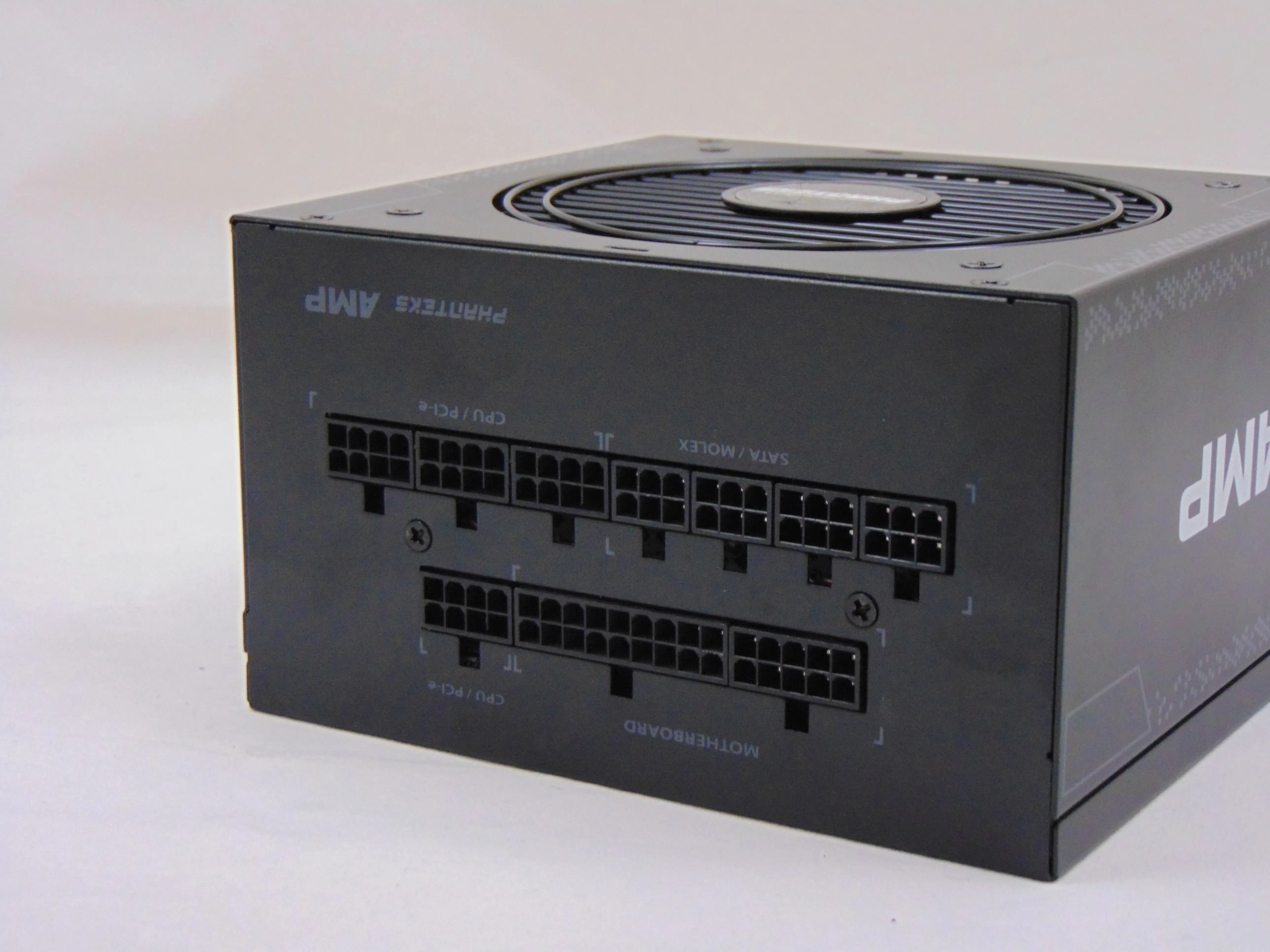
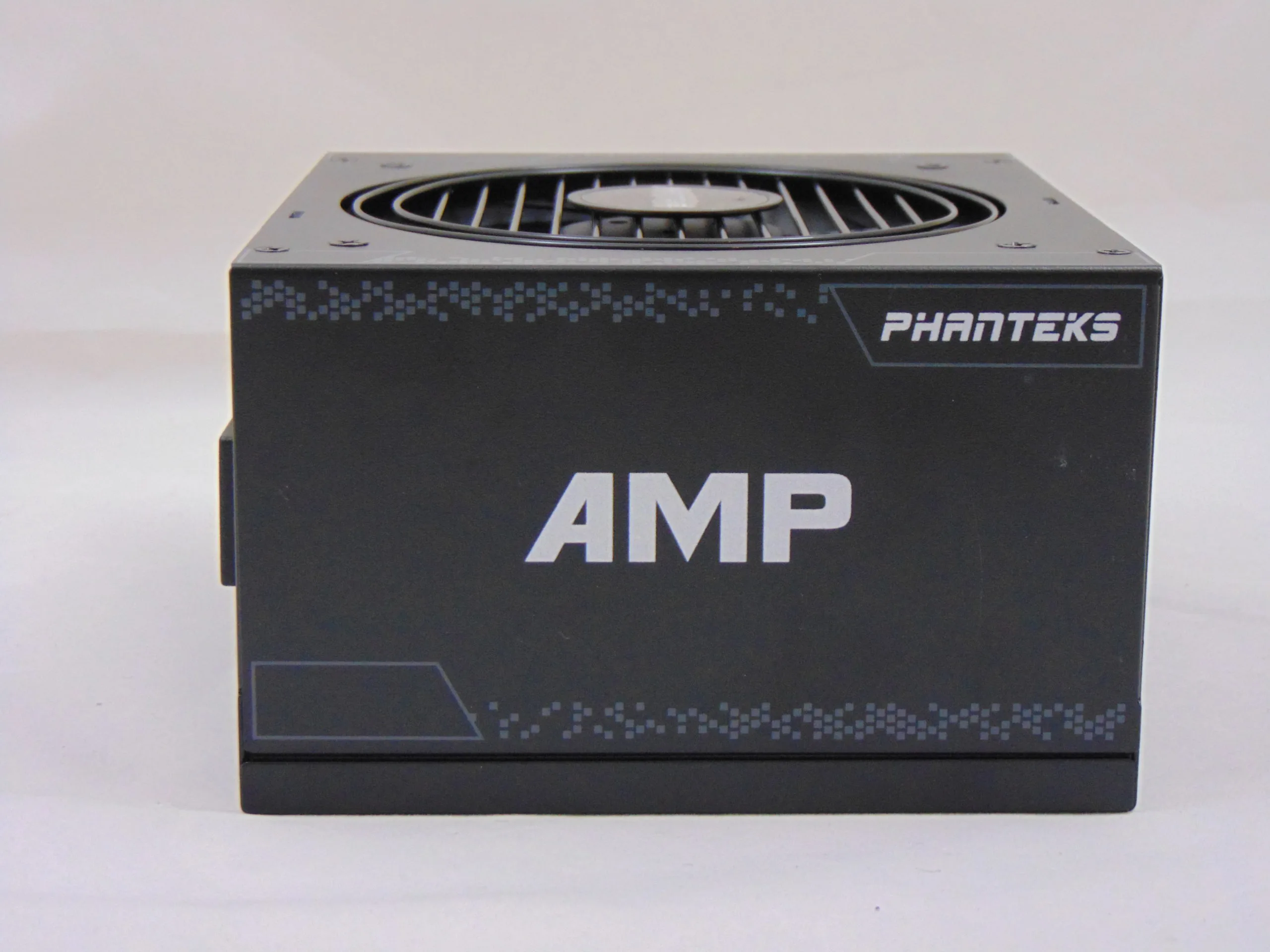
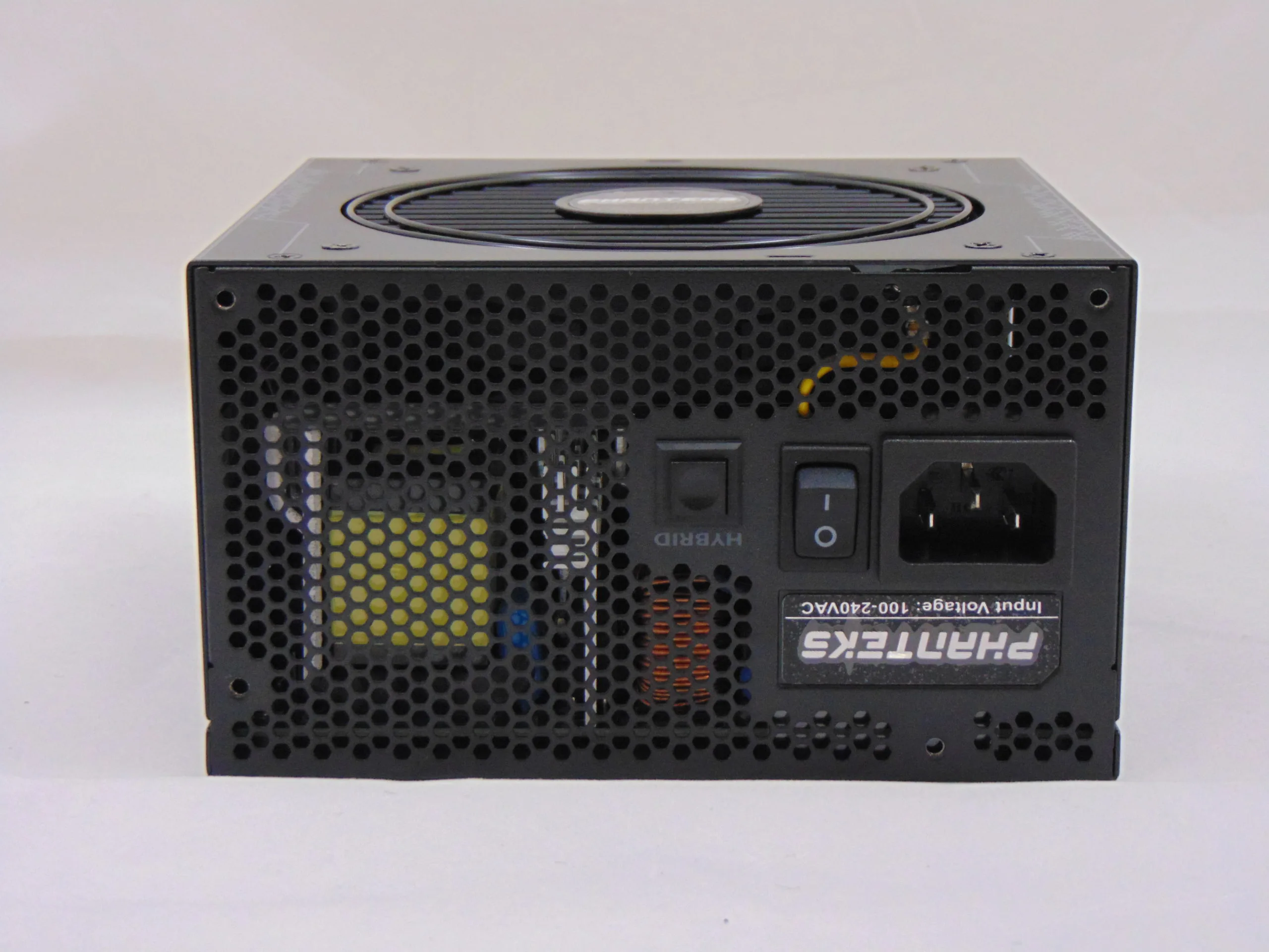
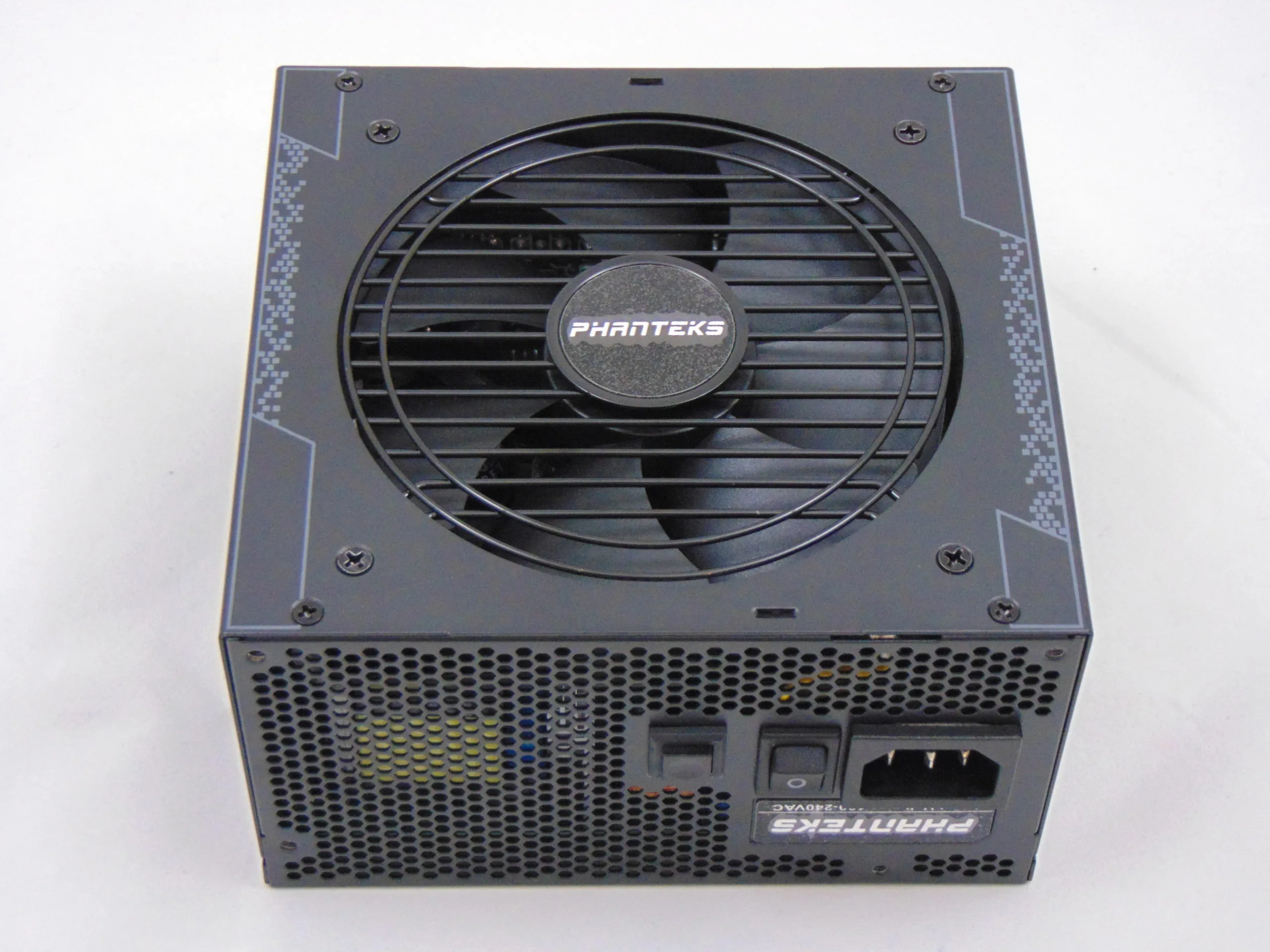
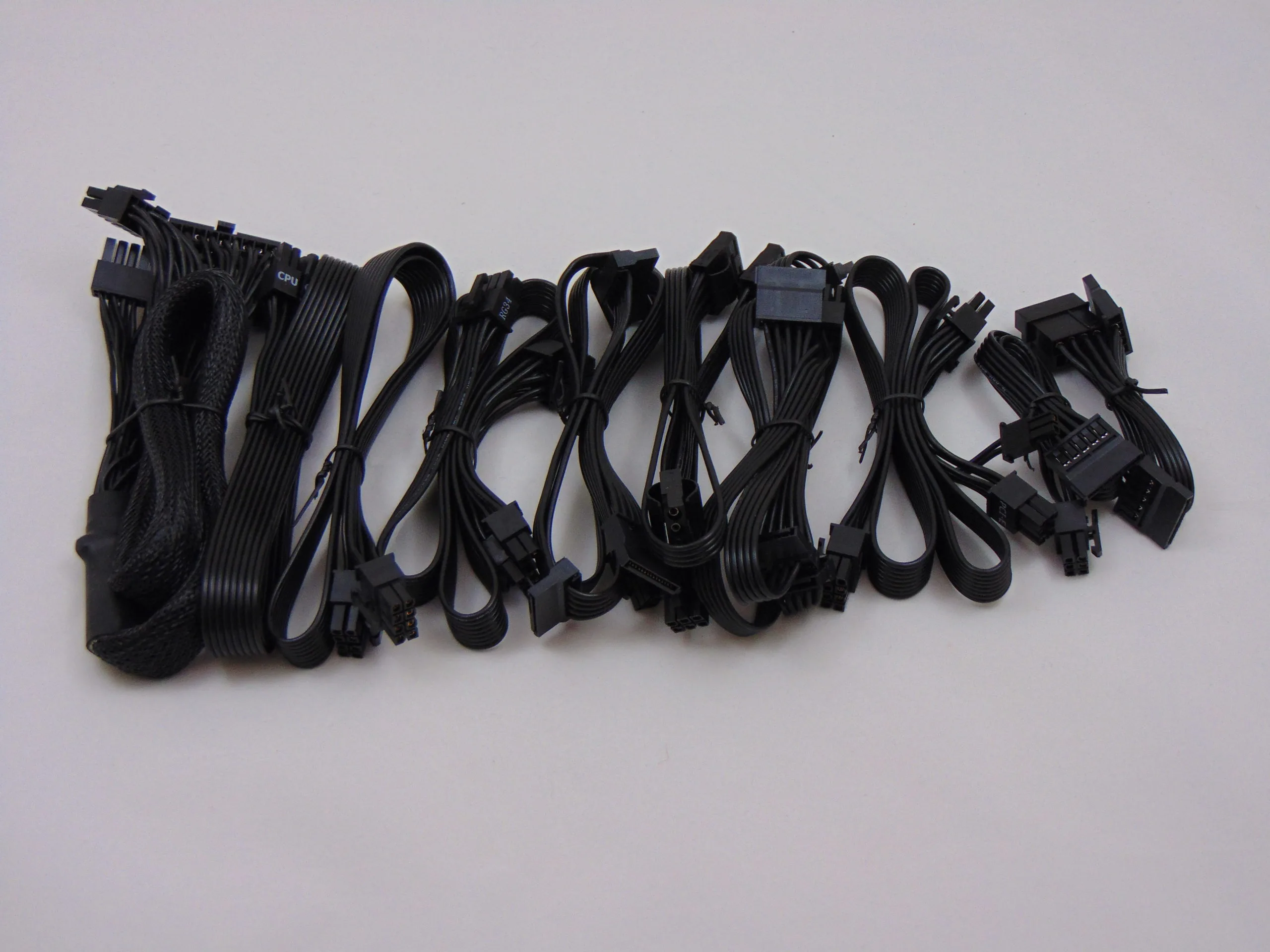
The power supply we are using today is the Phanteks AMP 750W. This particular unit is built by Seasonic and features an LLC resonant converter with a modern full-bridge primary. The secondary features a synchronous rectification and DC-DC VRMs for the minor rails. The power output distribution for this unit is similar to other 750W units in its class and reproduced below. Externally, this unit features a modular design and utilizes the basic Seasonic power cables.
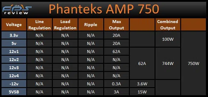
The AMP 750 is advertised as being a single 12v rail power supply with a capacity up to 62A (or ~99% of the unit’s capacity) if necessary. The minor rails (5v and 3.3v) have a capacity of 20A each and the combined capacity of those two rails is 100W. Combined with these outputs, we will be using the 24pin ATX connector, 8pin EPS connector, one of the 8pin PCIe connectors, and one MOLEX connector for our testing today. The remainder of the cabling will not be attached to the unit.
Thermaltake Dr. Power II
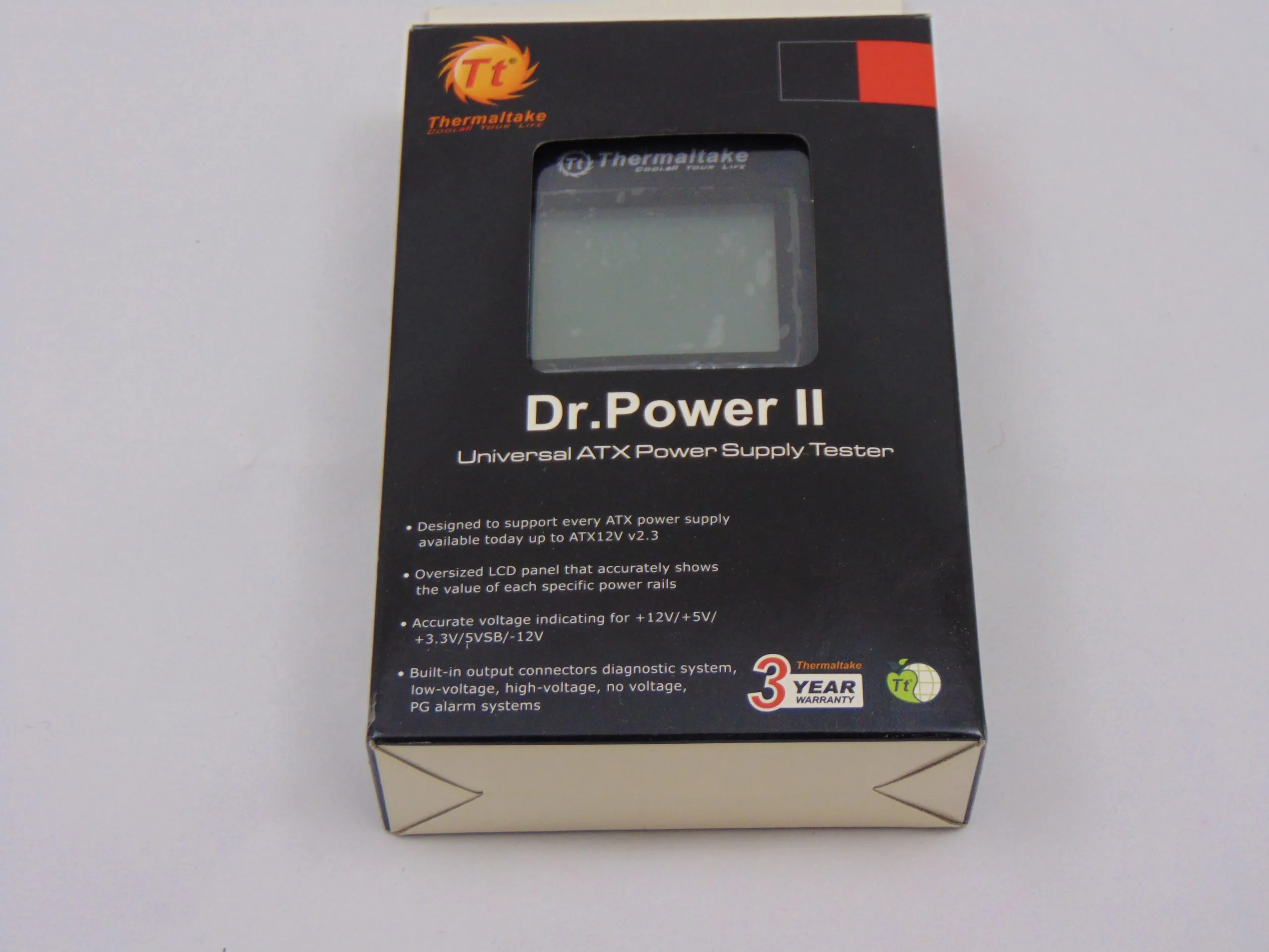
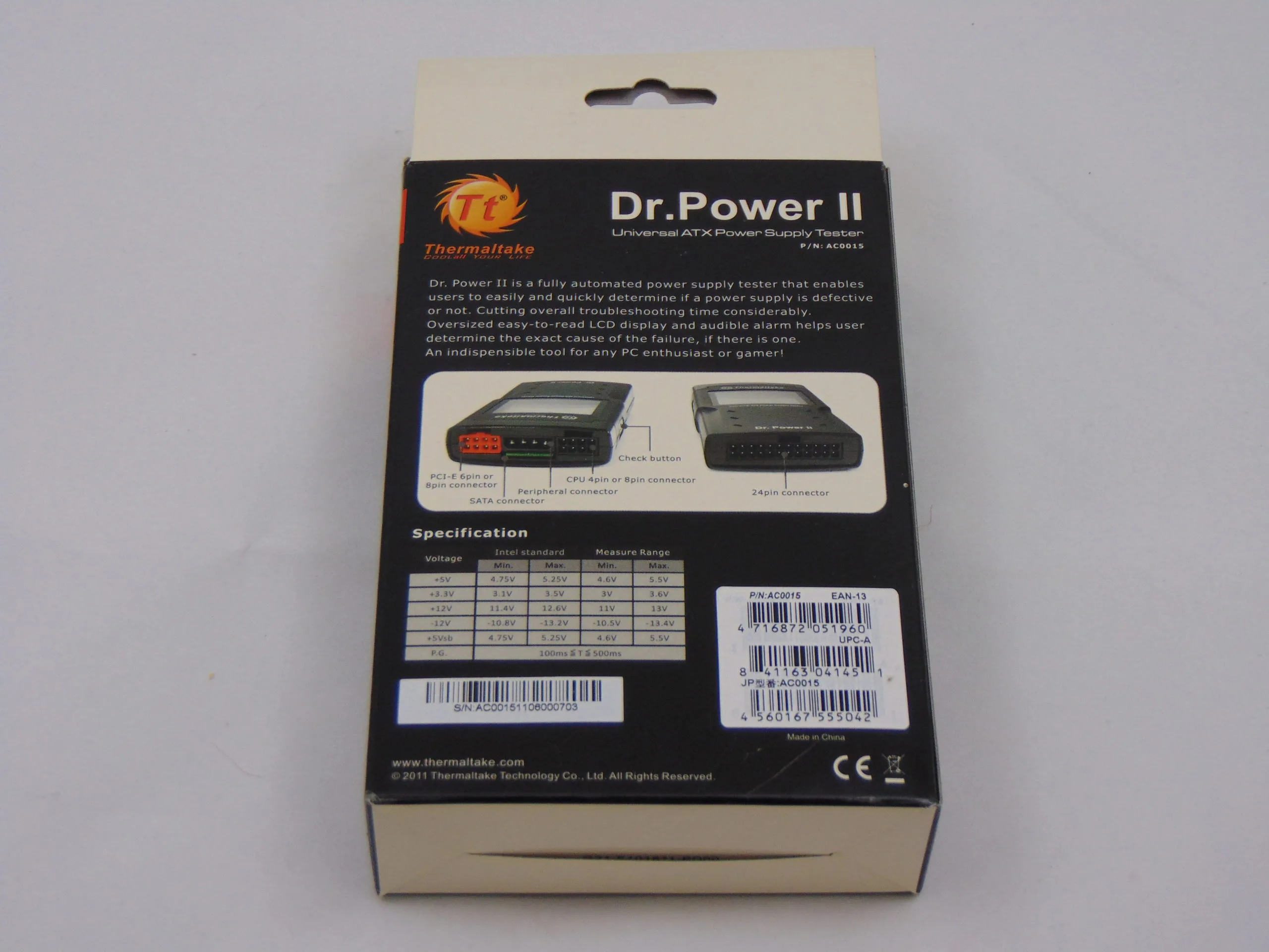
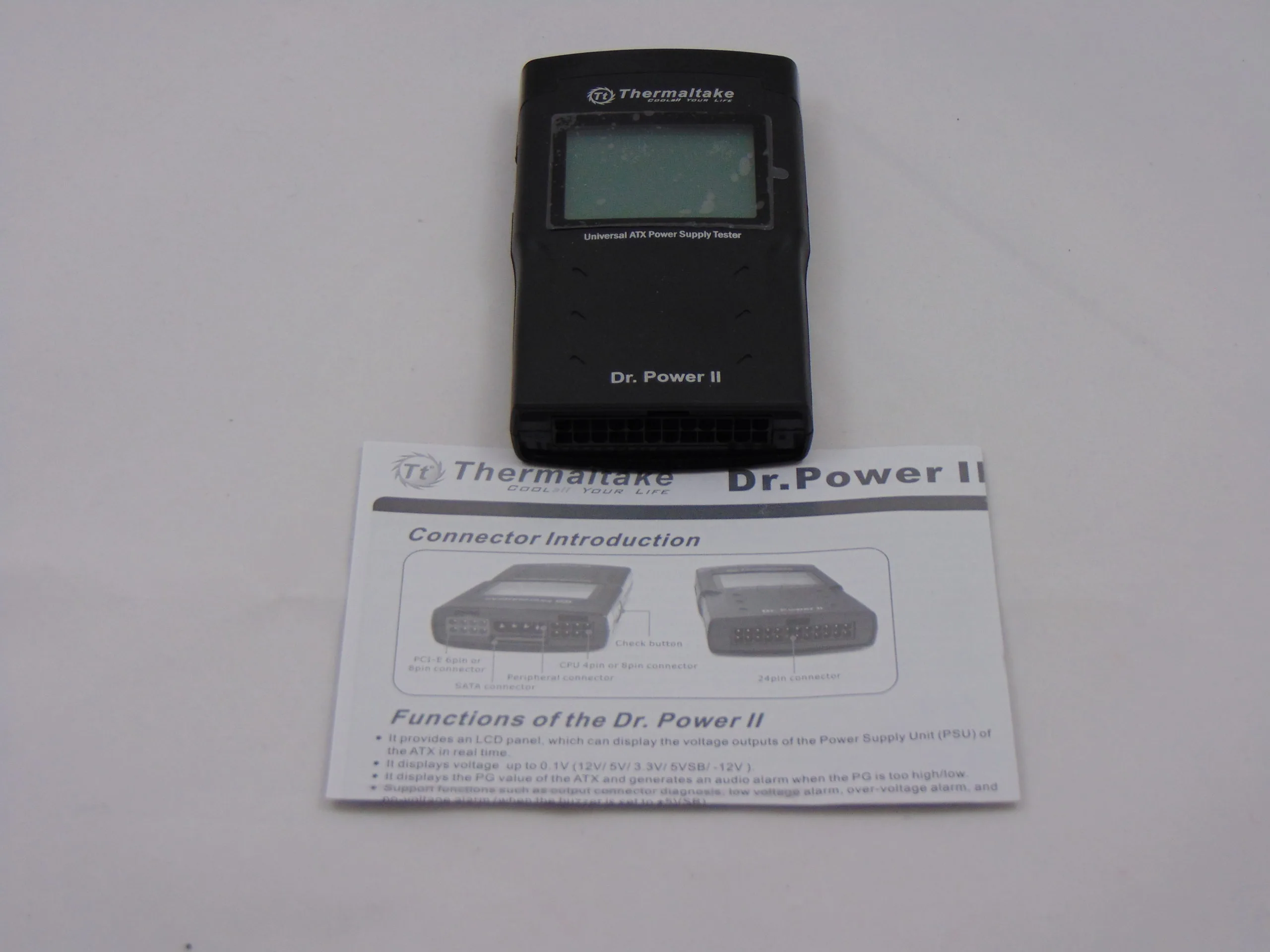
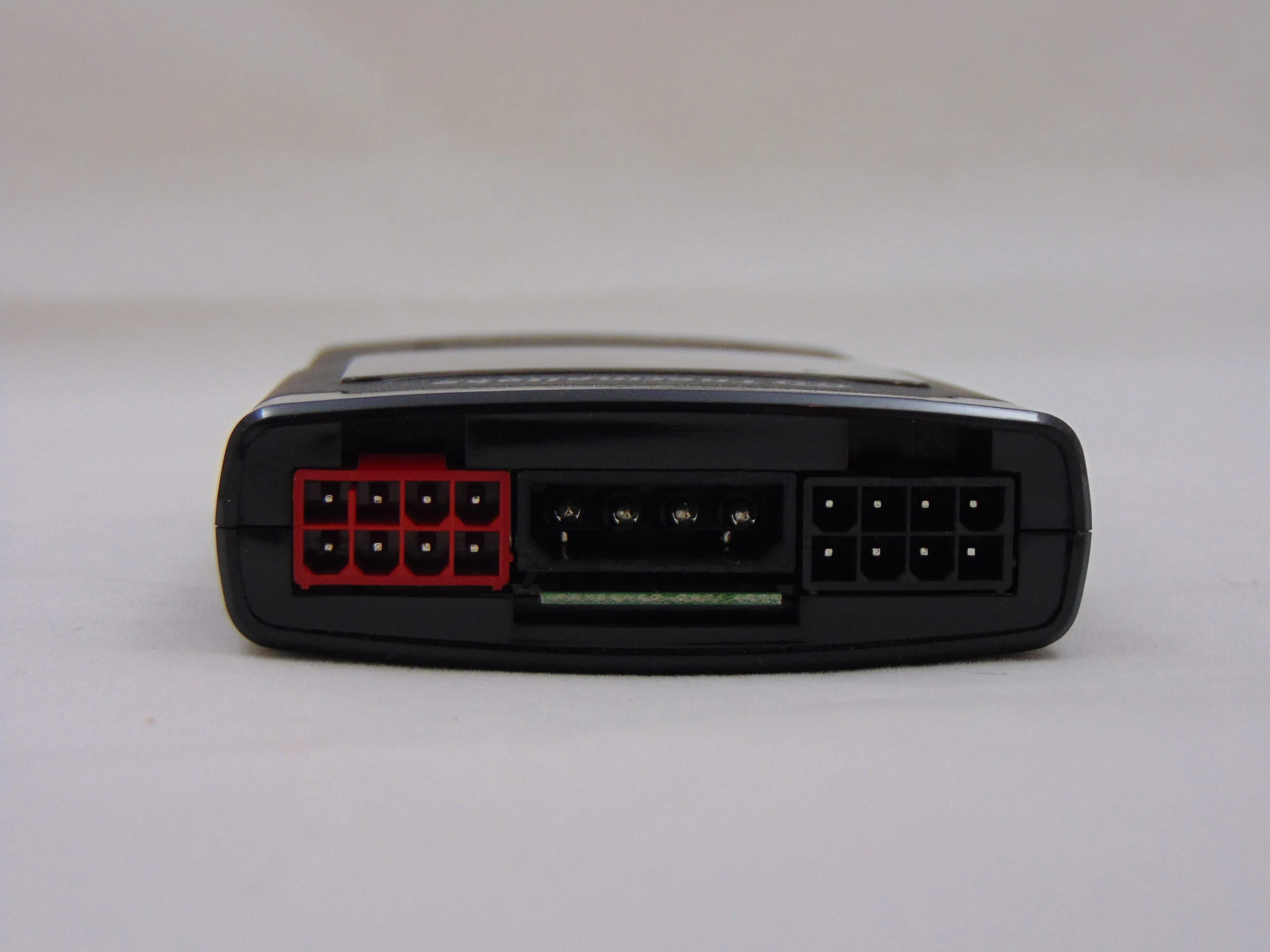
The Dr. Power II comes in a rather small box (not surprising) with a small window so you can see the display of the product inside. The front of the packaging carries some Thermaltake branding as well as some bullet-pointed listings of what the Dr. Power II is supposed to do. There is also a small label at the bottom that indicates that this unit has a 3-year warranty. On the back of the packaging, we find a labeled layout of the Dr. Power II indicating which cables on your power supply connect where on the Dr. Power II. We also get a table that lists the ATX12v standards for voltage outputs along with the measurement range of the Dr. Power II (reproduced below).
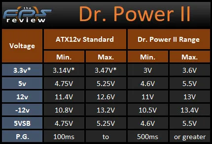
As we see here, the Thermaltake Dr. Power II claims to have measurement ranges that exceed the ATX12v specification limits. For test instrumentation, unlike a power supply, this is a good thing. Not so good? They got the ATX12v specifications for the 3.3v rail wrong. Also not so good, it looks like the unit only gives us one digit of precision past the decimal place in most cases. That is certainly less than we would hope for in a piece of test gear.
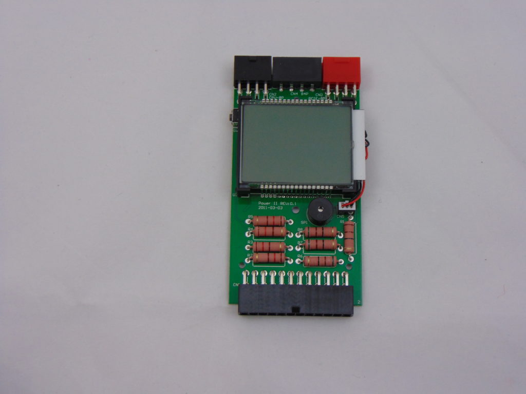
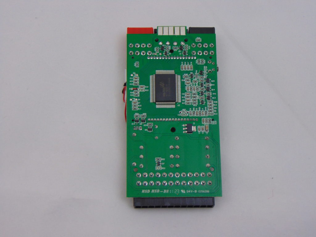
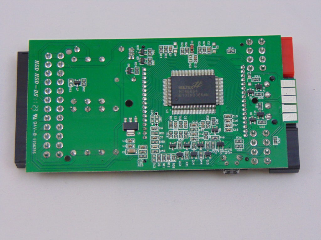
Once we crack the Dr. Power II open we find that the unit is compromised of a single PCB inside of the clam-shell enclosure. On the front of the PCB, we find a number of items. We find a smattering of resistors, a small speaker, the On/Off/Test button, the connectors for our cables, and, of course, the oversized LCD panel. When we flip the PCB over we find our circuit side here with our resistors connected in series for some rails (to increase the static load) as well as the Holtek microcontroller that is going to take our analog data and display it on our LCD display that was on the top side of the PCB.
All in all, this is a very simple affair which is not that surprising given the price point. Anything more than a simple resistor based design that will put a minimal load on the rails being tested would need some form of active cooling and/or active loads. Thus, making it larger and more expensive.
Now, with that all covered, let’s move on and see how things go when we start comparing our two different pieces of equipment!